Building a new Pattern Matrix with conductive thread
Posted Aug. 28, 2020 by Dave GriffithsWhile processor speeds and the use of computation in our society have increased enormously, it is significant that the materials of electronics construction itself (discrete components soldered on to resin printed circuit boards) has been broadly consistent for well over fifty years.
The Penelope project is concerned with re-evaluating histories of textile technologies with mathematical and scientific thought. The emergence of “wearable electronics”, in particular inspiration from Penelope collaborators and friends such as Ebru Kurbak and Sandra De Berduccy is important for us because it proposes a new constraints and possibilities ushered in by alternative materials with a rich and long technical history of their own.
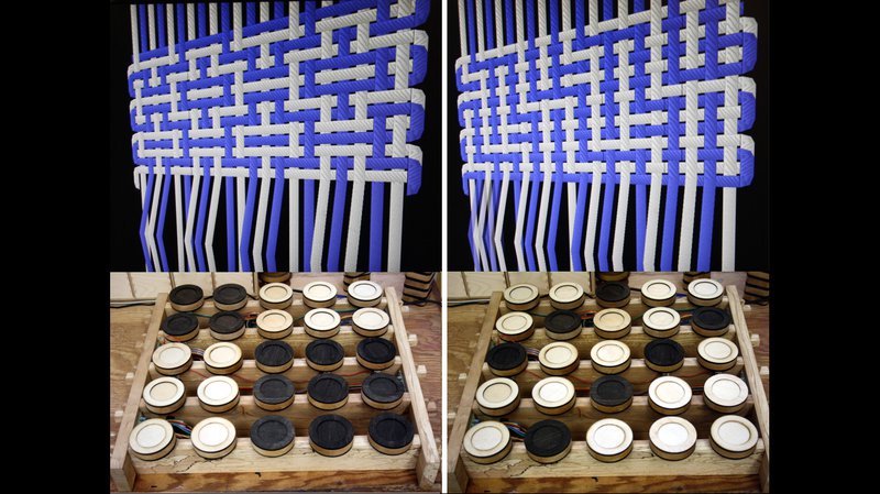
The Pattern Matrix is the Penelope project’s tangible interface for understanding the minds of ancient weavers, by presenting an immediate and graspable representation of weaving logic. This interface employs the use of magnetic sensors to read different types of tangible wooden block that can be oriented to emulate the notation system of weaving. The development of this machine has progressed via a winding path of different materials, each with their own culture:
- Extruded aluminium and 3D printed plastic: the initial version was constructed in conventional “maker” materials and techniques. These materials represent all the wonders and horrors of contemporary production – the convenience of standardised parts alongside fast 3D printed specialised components brings with it worries of both their past: unknown supply lines, worker conditions and ecological impact of e.g. aluminium extraction, as well as their future: all too rapid degradation of 3D printed plastic into microplastic particles consumed by marine life.
- Wood construction: from hand carved parts to fabricated CNC milling, wood as a material answers most of the questions posed above, with a traceable past (the material for one of our devices originated in a single tree in Cornwall) to a well understood future: reuse, compost or combust for heating. When we think of reuse and adaptability of technology, the culture of woodworking is also distributed far more widely throughout society than that of normal fabrication of contemporary digital devices.
- Textile construction: offers similar benefits to wood as a base material (compostable, reusable with long running culture of its own) but in the context of the Penelope project, allows us to explore some of the diverse links between textile material culture and that of computation. We can use it in a way to re-examine electronics as its own heritage material culture as we begin to explore the emerging field of wearable technology.
This text is an account of the challenges and discoveries of practical consideration for textile materials and interfacing them with traditional electronics, viewed under the particular technological lens of the Penelope project.
Basic techniques
Conductive thread is generally difficult to stitch directly, it’s certainly not a great idea to use it in a sewing machine as it behaves differently to plant or animal fibre. For this reason, “couching” stitch – where one thread is used to bind another along the surface of a fabric is often used to fix conductive thread in place, rather than stitching it directly. Initial tests with this approach were promising, however it was extremely time consuming as it has to be done by hand, and once sewn the conductive thread becomes more or less permanently fixed in place.
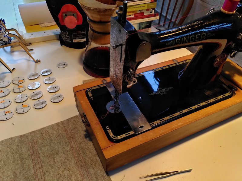
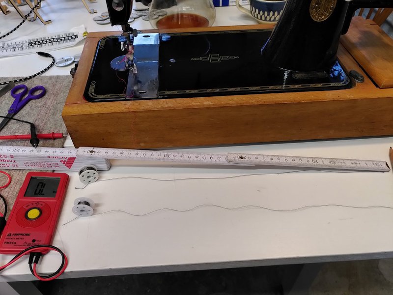
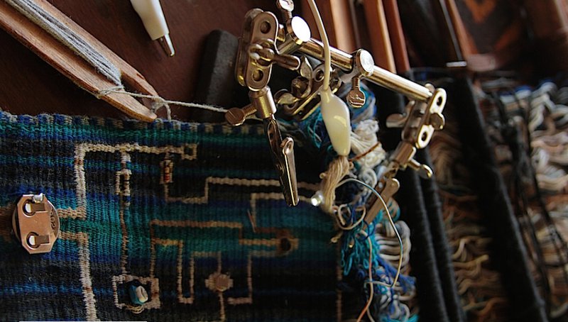
For these reasons we used a different approach, a kind of couch stitch in reverse, where cotton threads are stitched on a machine (a 1911 Singer, currently going through its second world wide pandemic) first to lay out the circuit, after which the conductive thread can be hand sewn though the machine stitch.
For the stitched version of the Pattern Matrix, the electronics were redesigned to minimise the connections required for the stitching, we increased the complexity of each of the 16 sensor circuit boards by giving each one its own small microprocessor, so they could be connected in series – ie. each one connects to the same four wires as all the others (known as “bus” connections) making the stitching itself very simple. Previous versions of the pattern matrix used parallel connections, where each sensor required its own separate connections (meaning 64 individual threads would be needed, rather than four).
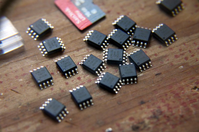
The tiny processors we used for this are Atmel ATTINY85, and cost less than 1 Euro each:
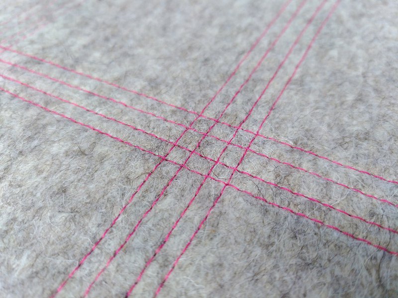
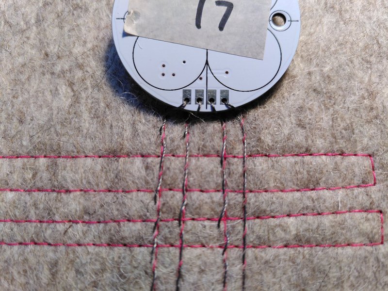
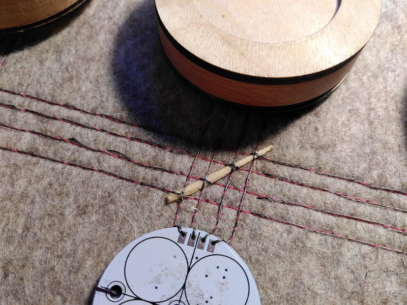
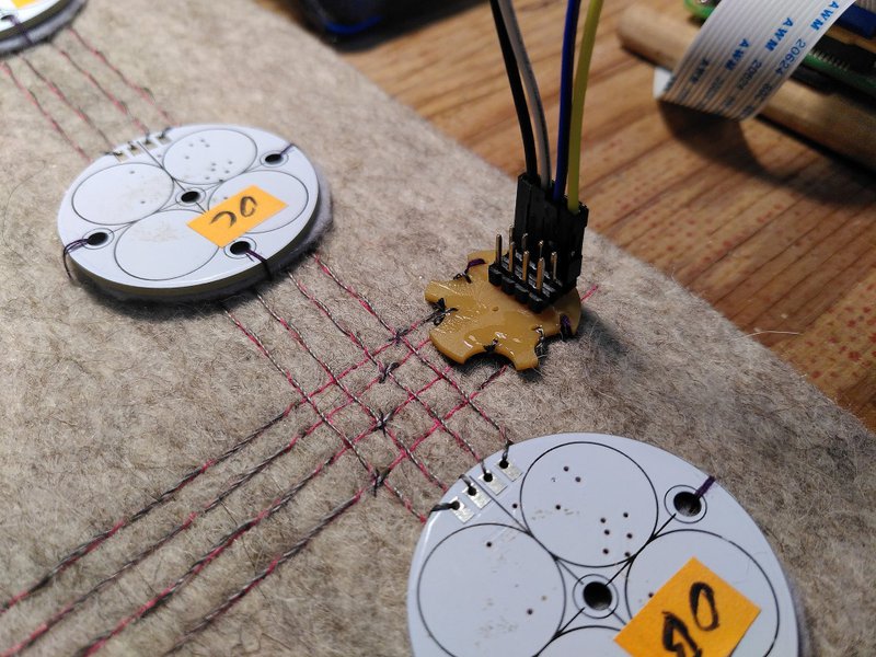
We can quickly stitch the circuit out with a sewing machine, here we have four groups of vertical stitches, each comprised of four connections, joined by a central horizontal connection.
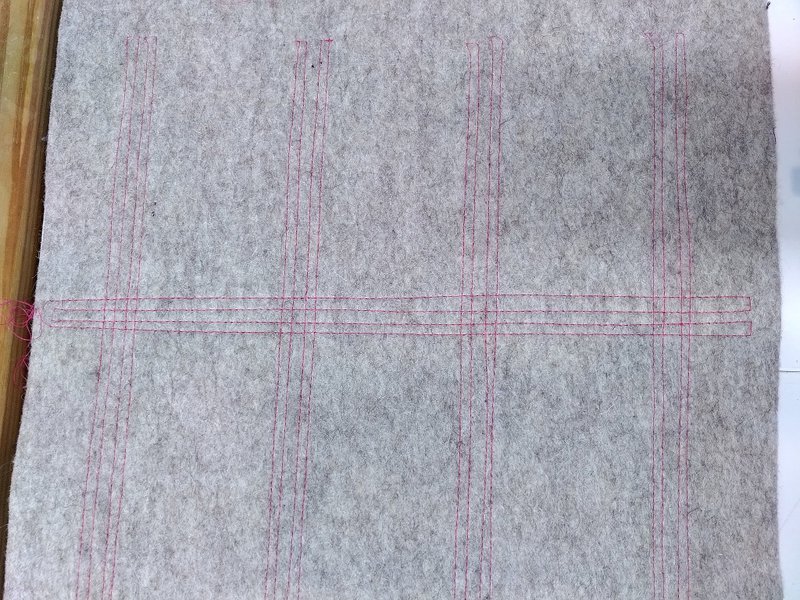
The central connecting stitches include crossing points, where we can distribute the power and serial data communication across the fabric from a single point – this turned out to be too ambitious and cause problems (more on this later). The four connections are power (which can be 3-5v), ground, serial clock and serial data for actually transmitting information on the sensor state – using i2c protocol, commonly used for sensor communications like this, but designed for circuit boards rather than conductive thread.
Learning the material properties of conductive thread
Once the circuit had been stitched in cotton, we could now look at the choices of conductive thread. We had two types to choose between, both purchased from Adafruit – and both made from 316L stainless steel (which interestingly is also washable). One was 2 ply, the other 3 – both are very smooth with no “fluff”. We experimented with cheaper options beforehand, and the important factor with conductive thread turns out to be its resistance. Cheaper conductive thread has higher resistance, which is suitable for some applications such as capacitance sensing or powering LEDs, but we need something more conductive for carrying digital signals over the distance we need.
The 2 ply thread is rated at 16Ω per 30cm while the 3 ply is 10Ω resistance. Previous tests with the 2 ply thread had demonstrated a voltage drop of over 1.5v across the distance required (at the current the Raspberry Pi supplying the 3.3v power provided). This meant the voltage was less than 2V at the sensors furthest from the power supply. While this is within the operating specification of the processors we use, it is well under the minimum 3v for the hall effect sensors to actually read the magnets.
We measured the resistance on our conductive thread, and it was slightly better than advertised: 14Ω per 30cm for the thin 2 ply thread 6Ω for the 3 ply, so decided to try the 3 ply. Using 5V provides around 3.4v in the worst case to the most distant sensors, so well within our specifications.
The stitching process
The idea of the “reverse couch stitching” is to sew the conductive thread by hand through the cotton machine stitch, without going through the supporting fabric – this is difficult to describe or photograph, so we adapted the Penelope thread simulation software to be used for visualising this structure:
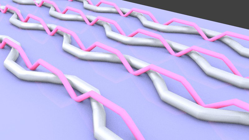
It turned out that you don’t need, or generally want – to have one crossing of conductive thread for every single machine stitch in all circumstances, but it is a good idea near the ends or around places that may cause tension. In the long runs between sensors it’s enough to skip 4 or 5 cotton stitches at a time.
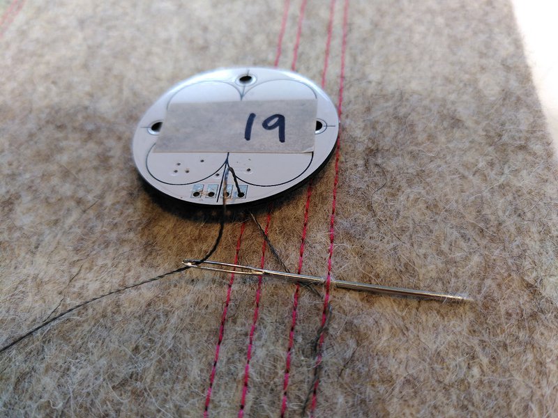
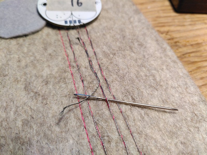
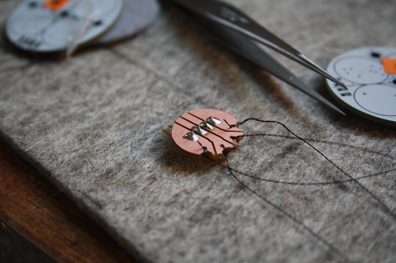
The conductive thread can then be looped around the circuit board connections. The holes on the PCBs are plated with tin all the way through the inside and on both sides. As long as you keep the stitching fairly tight around these connections, it provides a surprisingly reliable connection.
Here is a sensor with all of the four connections completed. The distance between the cotton stitching was only just wide enough to avoid short circuits – this will be slightly wider in future versions. It’s not a problem that the connections on the circuit board are closer than the stitching, as the circular shape means the conductive threads are held apart. The main change needed for the circuit board is to make the holes big enough for a small needle with conductive thread to pass through, and make little notches to accentuate the separation as well as protecting the conductive threads from wear. Due to the way conductive thread frays the instant you cut it, I had to often re-cut a small amount from the end before threading it through a new circuit board, which was time consuming (and meant quite a bit of waste too).
Luckily, extending the conductive thread if you run out is pretty simple. Knot tying is a particularly irritating procedure with steel thread that you need to avoid, as it has a tendency to magically undo itself. It turned out much better to simply have a long area of overlap, as shown below – and use the reverse side to keep the ends out of the way. For this reason it’s also important to use backing fabric to protect any connections underneath from surfaces.
A good technique to minimise fraying steel fibres is to use nail varnish to seal the ends of the conductive thread. This has the additional advantage of reducing the chances of stray “hairs” (more on them later) causing tricky to find short circuits.
To begin with I was very careful to test each sensor as it was stitched in place. This is because if there is a problem, it’s a lot of work to replace them after the row has been fully stitched in.
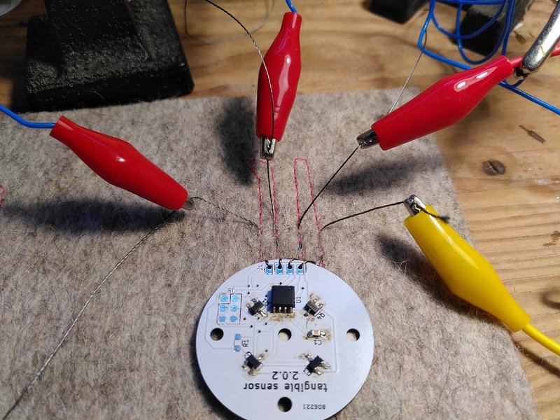
Here you can see the four hall effect sensors (each used for reading one magnet in the tangible blocks), the integrated circuit microprocessor and a decoupling capacitor to smooth out noise in the power supply. There are thin circles of felt used to prevent the soldered connections on the board from touching the conductive thread when they are folded into position.
Once there were a couple of rows of sensors done it was time to think about the central “bus” that connects all four rows together.
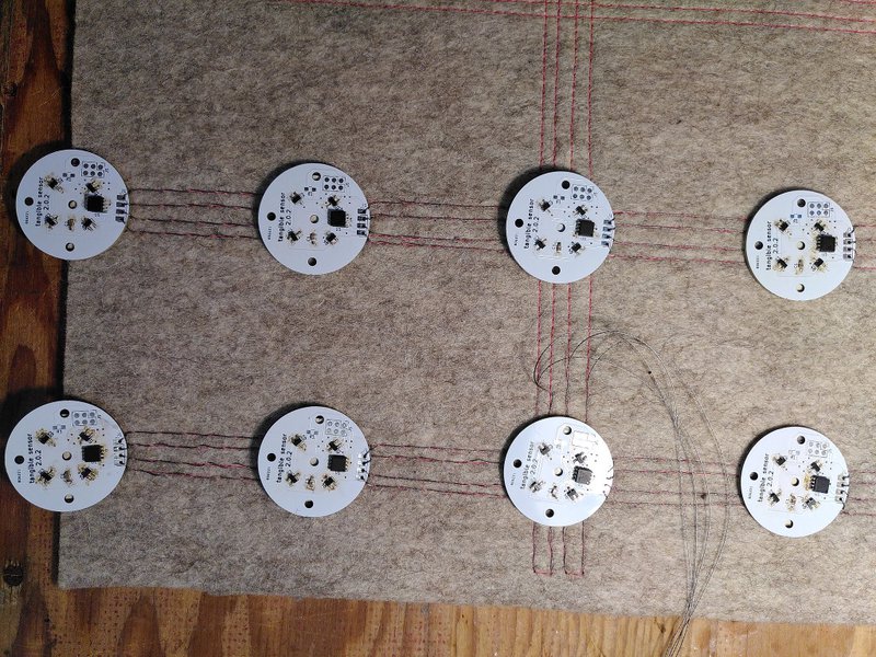
This is a complex procedure as we can’t just keep sewing conductive thread across the surface of the felt as we will just connect all of them together. We can use the felt itself as a insulation – and we can do this by flipping the side that the conductive thread is stitched on.
This is a close up of one of these crossing points, each connection is made by tying the vertical thread to the horizontal one to make the connection. It soon became apparent that it was important to be able to optionally isolate sections of the circuit for testing purposes. Small wedges of wood could be used to disconnect the sensors. This is not a common technique with conventional circuit boards, but you could imagine more advanced methods here, for example using conductive snaps for the same purpose.
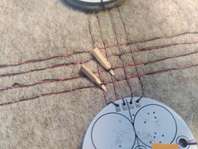
As mentioned earlier, these crossing points were the cause of a lot of problems – and a lot of different techniques were tried to make them more reliable. One was using a sliver of wood to provide tension to force the connection together.
However, despite the fact that power distribution seemed to work well this way, it caused many intermittent problems with the serial communication. The main issue seemed to be grounding problems – the stray capacitance represented by all these close connections made reading the sensor data unreliable. It may be possible to use a large conductive fabric ground plane sandwiched underneath the fabric to alleviate this, in much the same way as you would with copper fill areas on printed circuit boards. In this case we decided to remove these troublesome cross connection lines entirely and connect them using more conventional means.
Testing and fault finding with conductive thread
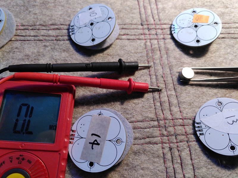
Short circuits mainly came from unavoidable tiny fragments of conductive hair from cutting the thread. Cleanliness is very important as this can be a big problem, even with simple circuits. Electrically these hairs also exhibited some interesting behaviour, as they often wouldn’t completely connect, but instead would form a capacitor somewhere. For example, everything would appear fine using a multimeter to test the circuit, until power is applied, which causes an immediate low resistance across the threads which would slowly climb over time as the charge built up.
Luckily enough, we can use the fact that the conductive thread is steel (and therefore magnetic) to track down exactly where these situations arise. You can connect a multimeter across two threads that exhibit this problem and hover a strong magnet around the connections. Even if the problem is on the reverse side of the felt, the magnetic field disturbs the tiny hairs just enough that you can register a change in resistance to pin down where the problem is.
Interfacing with the wired world
So called hard-soft connections are a big topic in wearable electronics, a famous blog post in the KOBAKANT DIY Wearable Technology Documentation lists many ways to do this. We began our investigation by milling a custom board with nice big notches to separate the threads out, which we could solder standard pin connections to.
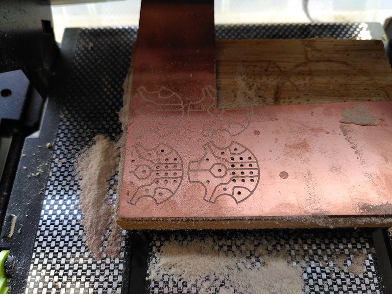
These connectors were the one place that required the conductive thread to be knotted – we used nail varnish to seal them permanently which seemed to work well enough. However, as these holes are not plated all the way through like the commercially manufactured sensor circuit boards, and as they are copper rather than tin – the connection is not good enough. In addition to the resistance of the thread itself, this added a 20-40Ω drop which was too high for our purposes.
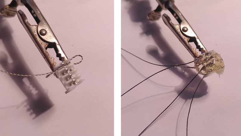
The second, much more successful approach was to avoid all knotting or copper connections and re-purpose a standard Insulation Displacement Connector (IDC). These work by having tiny conductive blades that cut through the insulation on wires and make a non-soldered connection with the conductor inside.
These can be used with conductive thread by looping them between the connection blades (the doubling gives them a bit more connection area and wedges them in) and sealing the whole thing with glue. This can then be trimmed and cleaned up up afterwards, with no need for knots and much better electrical conductivity.
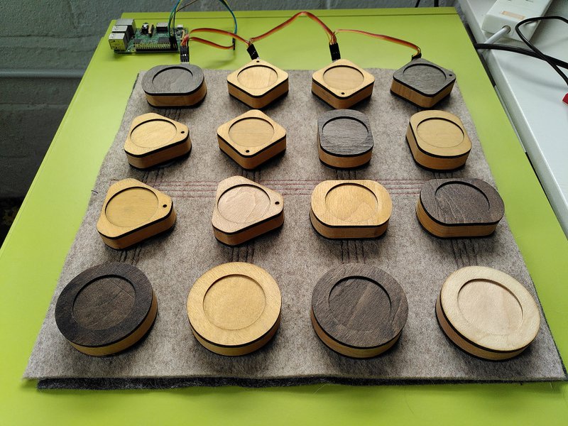
Here are the new connectors, one for every row of sensors with an external cable to connect them all to a Raspberry Pi, which can connect and talk to each of the sensor processors individually.
Some thoughts
The switch to this new construction technique has been a long learning process, the materials and methods involved demand respect and require new inventions and different ways of tracking down problems to be developed. Using serial communication over thread was a risk which paid off, as it is definitely outside the design parameters – but seems reliable enough for our needs. During the testing process we tried reducing the bit rate of the serial communication, but this seems unnecessary as once you have it working it’s fine at the “standard mode” of 100 kbit/second.
Fabric presents a much more malleable and modifiable material than hard PCBs, we used the same fabric base to entirely reconstruct this circuit twice, with a lot of rework of the connections trying different ideas. Using normal methods this would have involved many revisions of circuit boards, and a lot more waste. This also leads to more scope for future expansion of circuits, rather than traditional electronics that are in most cases “fixed” once constructed.
This is of course a hybrid approach, with a combination of PCBs and fabric – I think the next direction to take this in would be good to look at moving more of the components into soft form – certainly something to think about for our woven robotics.
Weaving the circuit directly into the structure of the fabric as it is made, as in the work of Sandra De Berduccy is the most exciting possibility here – this could make the process much faster as you could hook into existing connections instead of needing to sew them. If conductive threads could be incorporated into the warp and weft in a similar way as a breadboard for example, fabric could be used as a reusable basis for electronics construction in a similar manner – providing a reusable and reconfigurable substrate suitable for both prototyping as well as a highly durable end result.
Created: 15 Jul 2021 / Updated: 18 Oct 2021


